Sign in






DDM Function of Optical Modules
< BackDDM Function of Optical Modules
In fiber-optic links, faults are often difficult to detect. Issues such as gradual optical power degradation, laser aging, and connector contamination may persist for weeks before a complete link failure occurs, manifesting as occasional packet loss or transmission errors. If troubleshooting only begins after the link is completely down, business losses may have already occurred. The DDM (Digital Diagnostic Monitoring) function of optical modules is designed to address precisely this problem.
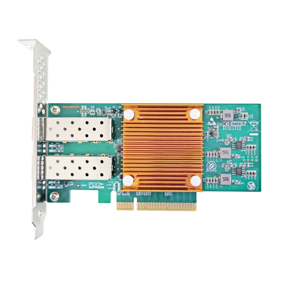
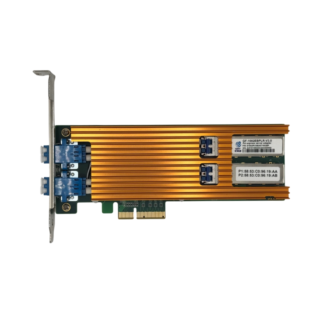
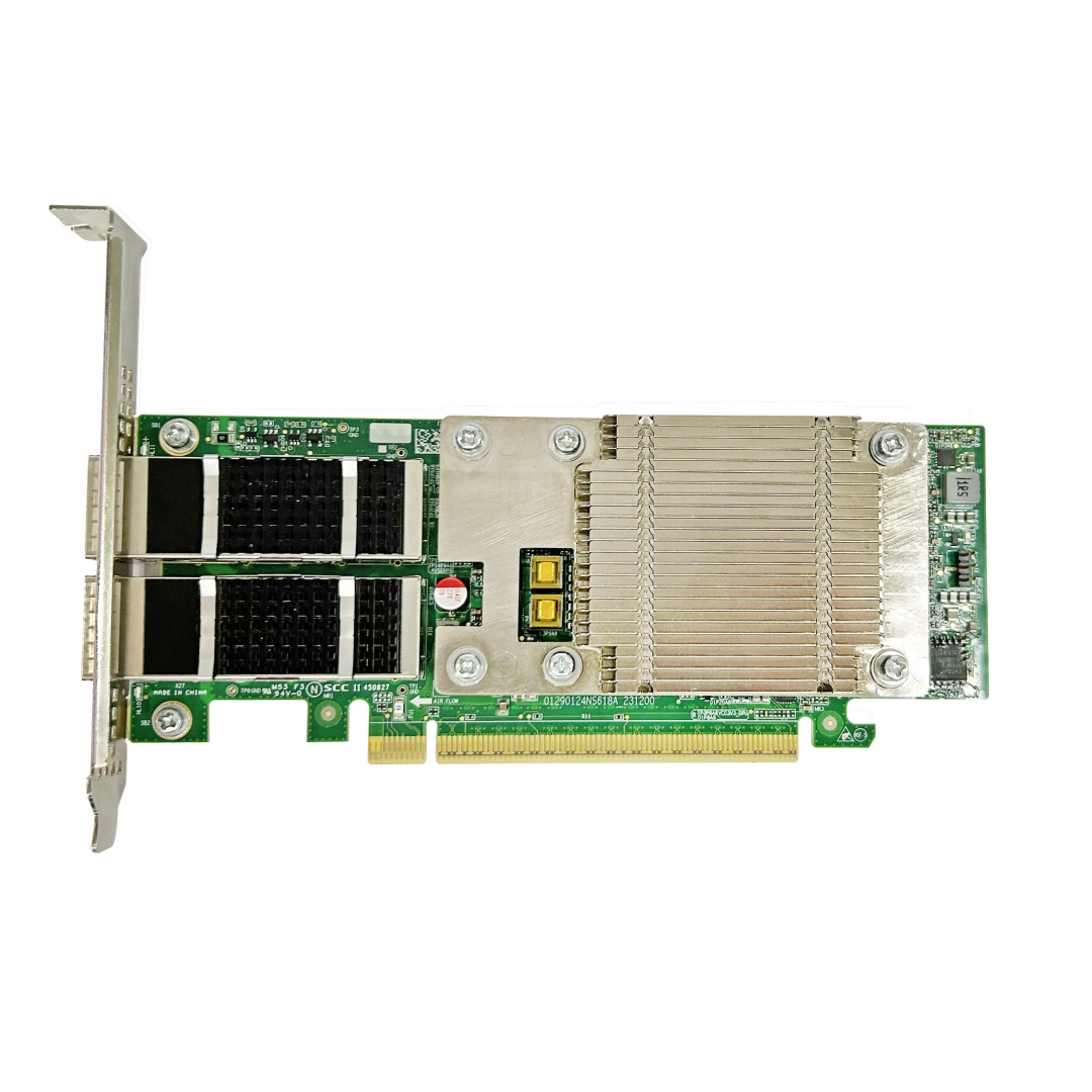
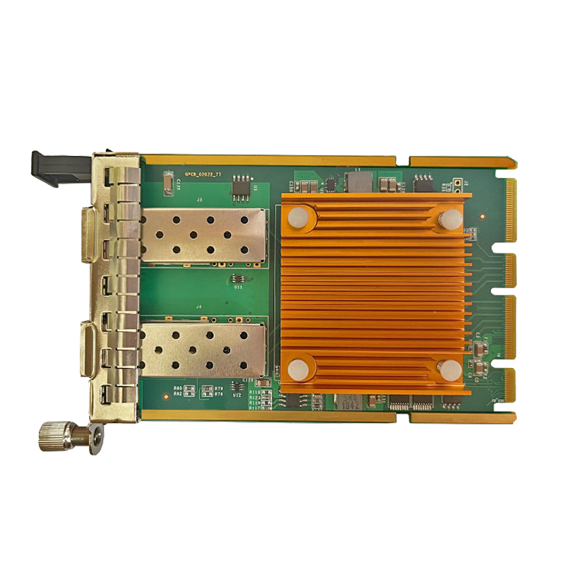
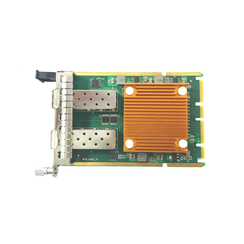
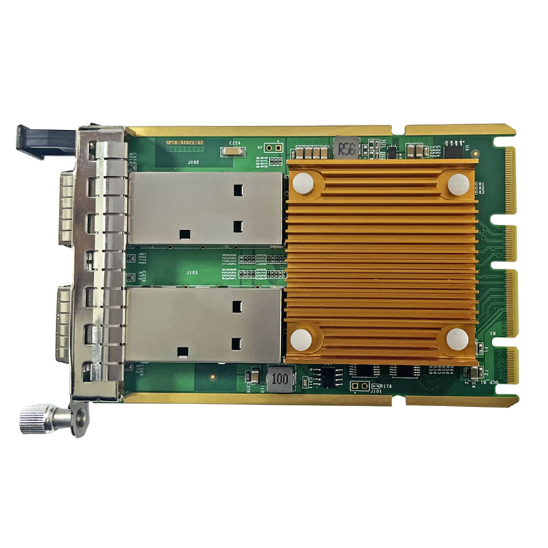
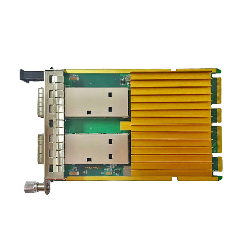
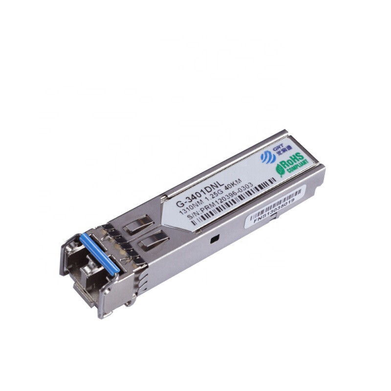
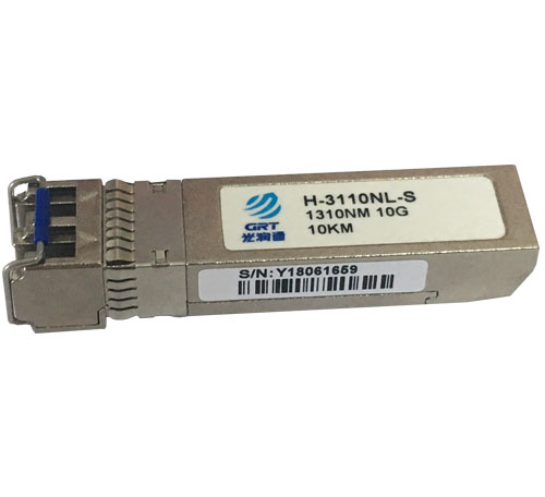
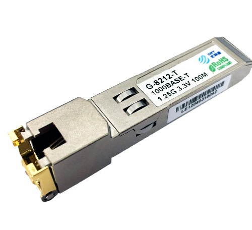
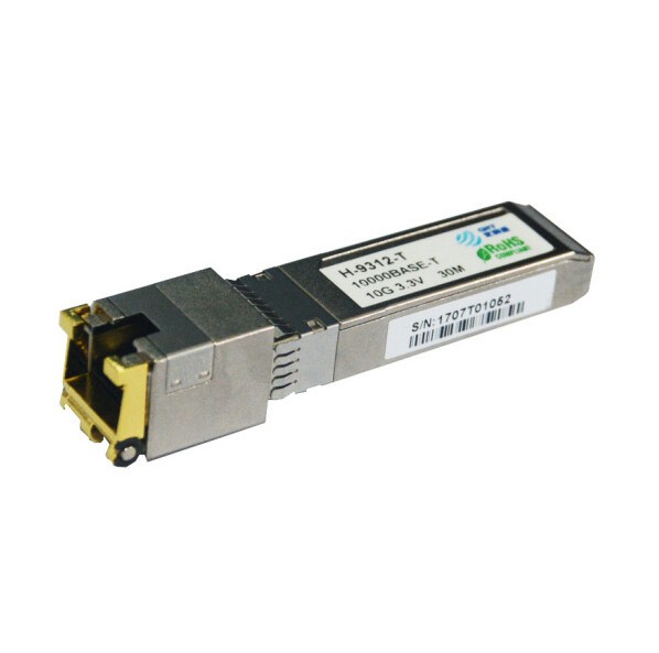
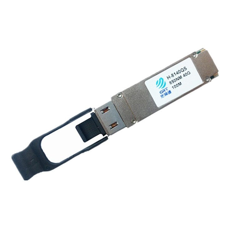
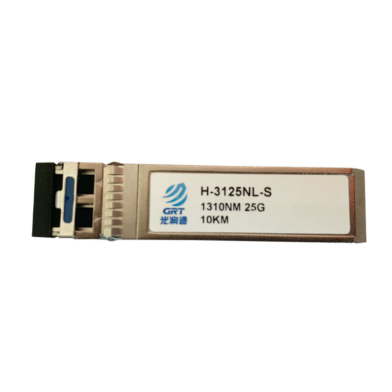
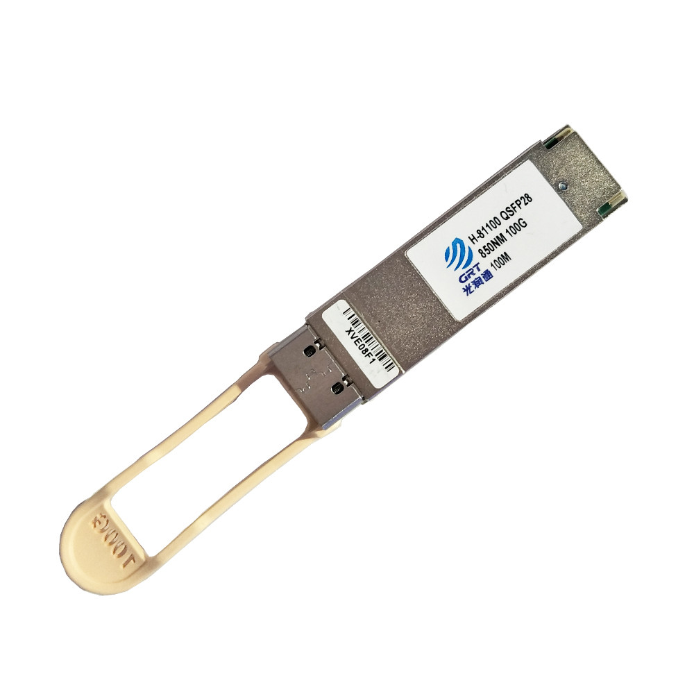
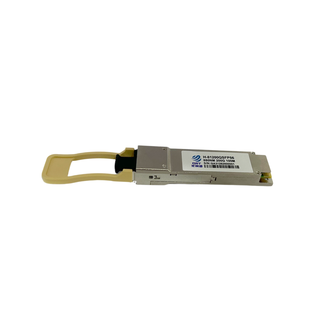
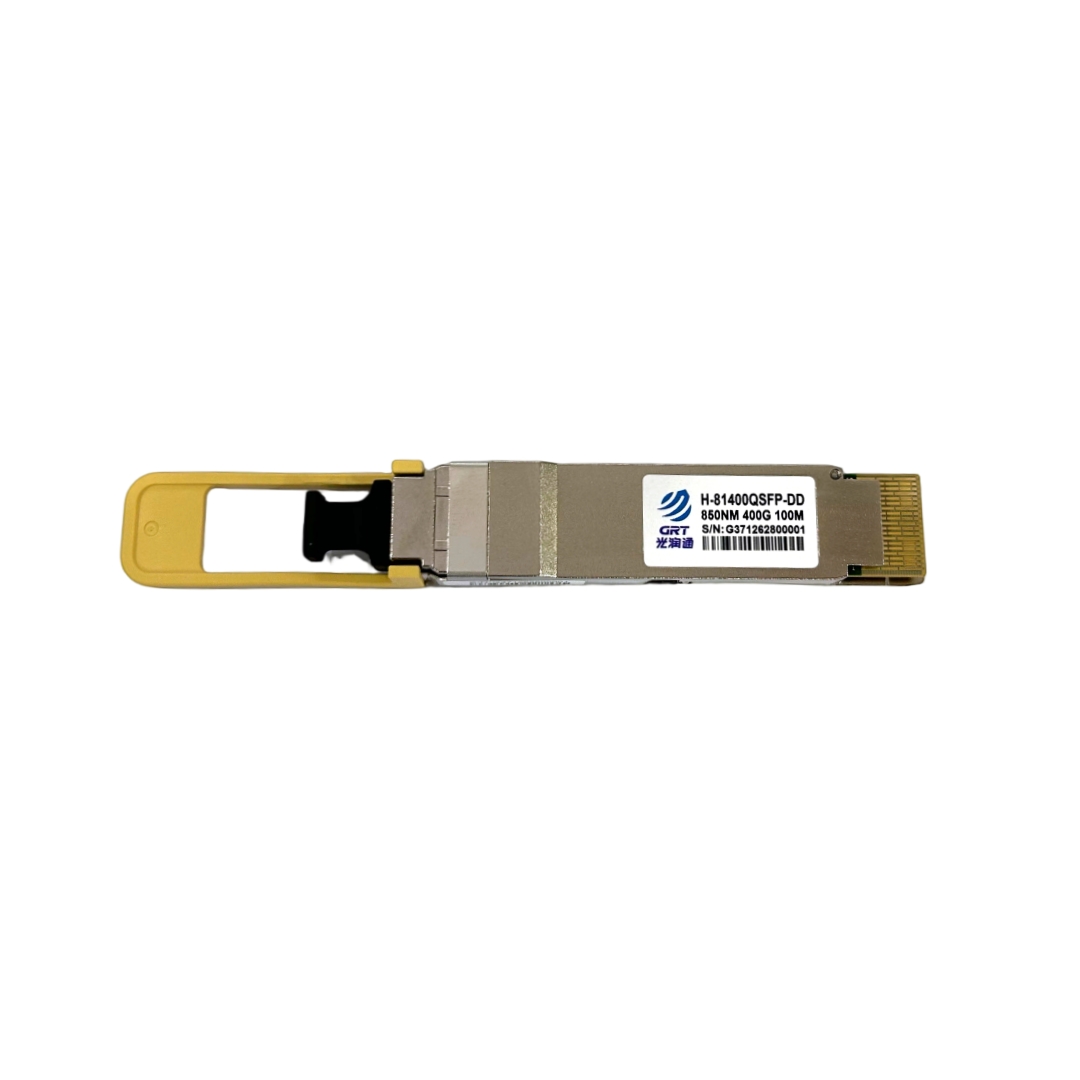
DDM uses built-in sensors to monitor key parameters of an optical module in real time, including temperature, supply voltage, laser bias current, transmit optical power, and receive optical power. Users can read these parameters through NIC drivers or management software. Originally designed for telecom-grade applications to predict optical module lifespan and locate faults, DDM has now become a standard feature of enterprise-grade optical modules. Most optical modules offered by GRT fully support DDM and work seamlessly with GRT network adapters, providing users with visual link health monitoring.
Each DDM parameter has its normal operating range and alarm thresholds. For temperature, commercial-grade optical modules typically operate from 0°C to 70°C, while industrial-grade modules operate from -40°C to 85°C. Excessive temperature accelerates laser aging and affects receiver sensitivity. The supply voltage is generally 3.3V ±5%; abnormal voltage may indicate a problem with the module's power supply circuitry or an internal short circuit. Laser bias current is a key indicator for predicting lifespan: as the laser ages, the bias current gradually increases to maintain constant optical power. When the current exceeds 1.5 times the factory-set threshold, replacing the module is recommended. Transmit optical power below the specified minimum may prevent the remote end from receiving the signal, while power above the maximum may damage the remote photodetector. Receive optical power that is too low (below the sensitivity threshold) indicates excessive fiber-link attenuation, potentially caused by excessive fiber length, connector contamination, or high splice loss. Excessively high receive power may damage the receiver.
In practical operations and maintenance, DDM can be used for fault warning, troubleshooting, and acceptance testing. By reading DDM data regularly, operators can identify a sustained increase in bias current or a gradual decrease in receive optical power, allowing them to schedule module replacement or link cleaning in advance and avoid unexpected failures. When CRC errors or link instability occur, checking whether receive optical power is within the normal range helps quickly determine whether the problem lies in the optical link or the equipment. After fiber-link installation, DDM can also be used to read receive optical power and verify whether link attenuation meets design requirements. On Linux, the command ethtool -m can be used to read optical module DDM information (provided the NIC driver supports it). The output includes current values, thresholds, and alarm flags for each parameter.
By making effective use of DDM data, optical modules can be transformed from “black boxes” into observable “dashboards,” enabling preventive maintenance of fiber-optic links and significantly reducing the risk of service interruptions caused by network failures.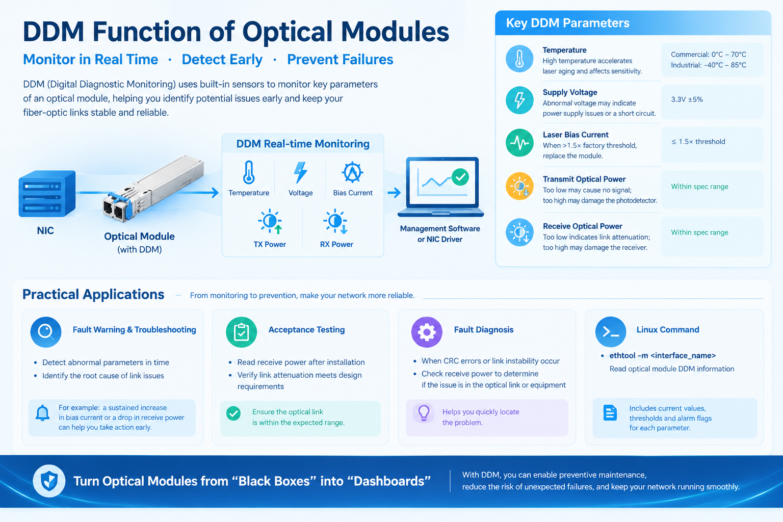
- Prev: Precision Time Protocol (PTP)
- Next: None
Latest information
- DDM Function of Optical Modules
- Precision Time Protocol (PTP)
- How NIC Interrupt Moderation Reduces CPU Load but Introduces Latency and Jitter
- The High-Performance Network Revolution in the AI Era: RDMA
- NAS Storage Network Upgrade Guide
- Why Does Upgrading Your NAS to 2.5GbE Not Improve Network Speed?
- What Is an OCP 3.0 Network Card?
- The King of Cost-Effective 25G NIC: In-Depth Analysis of Guangruntong (GRT) GH2502EM-V4.1