Sign in


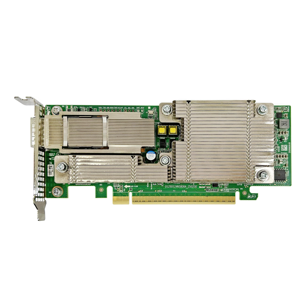
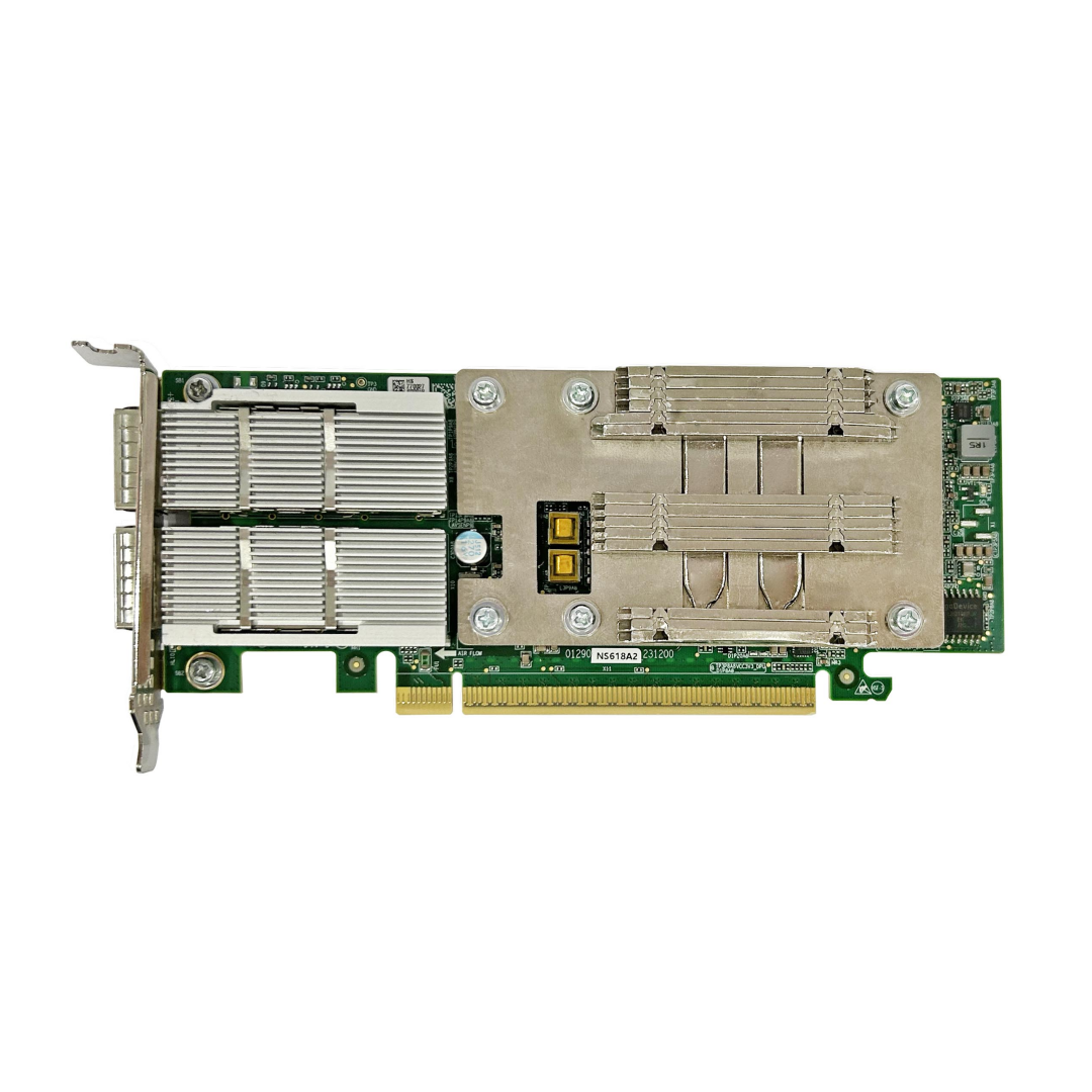
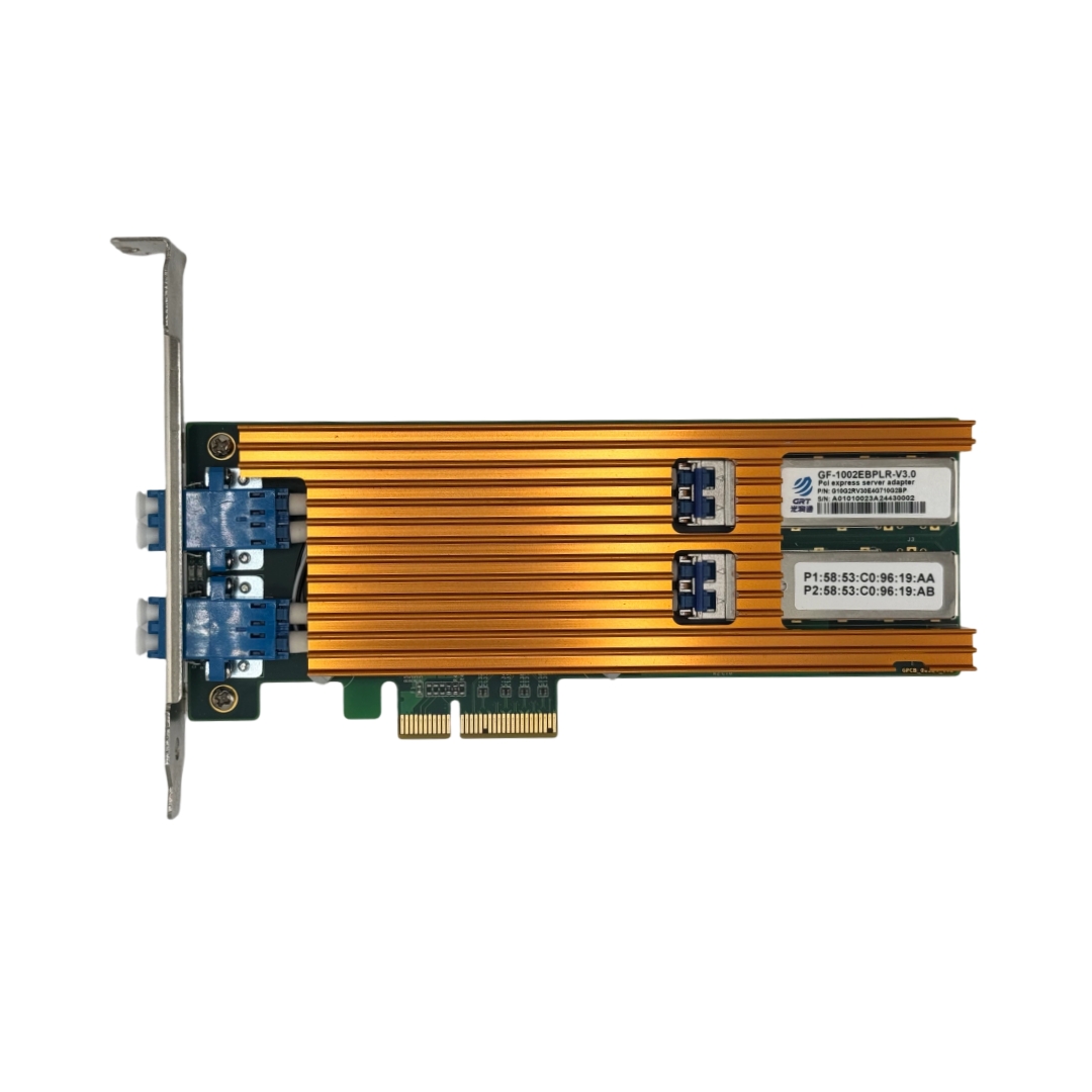
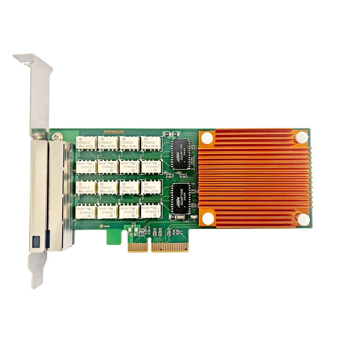
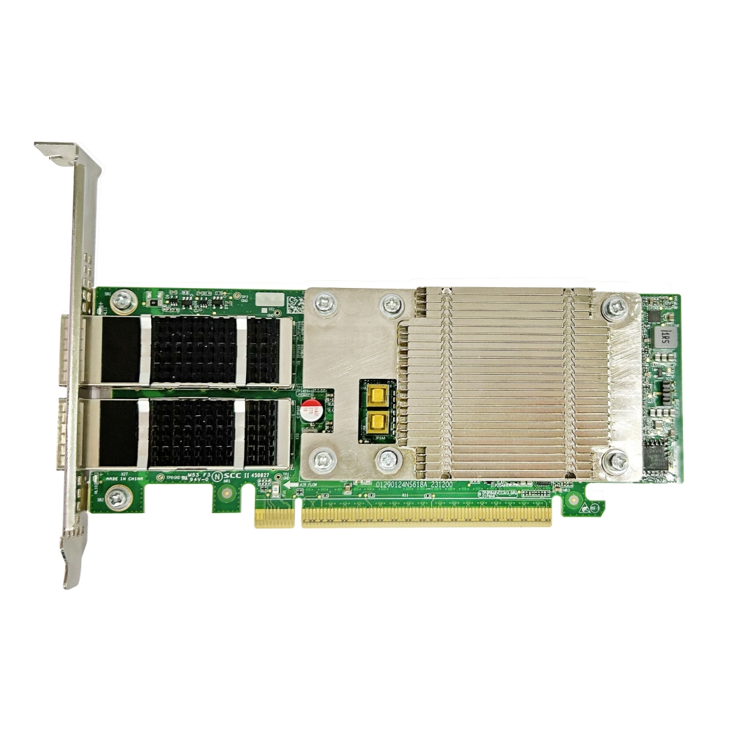

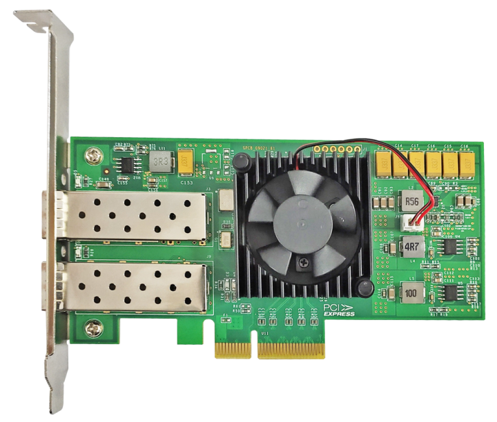
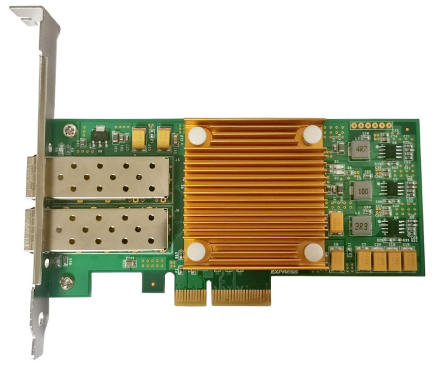
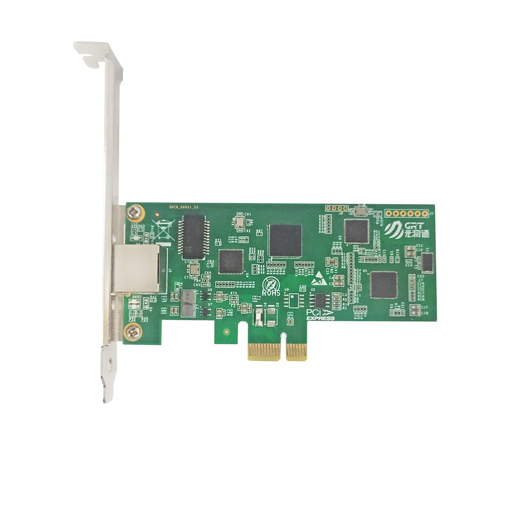
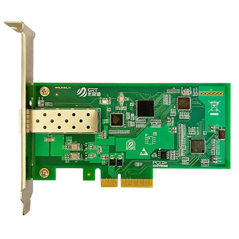
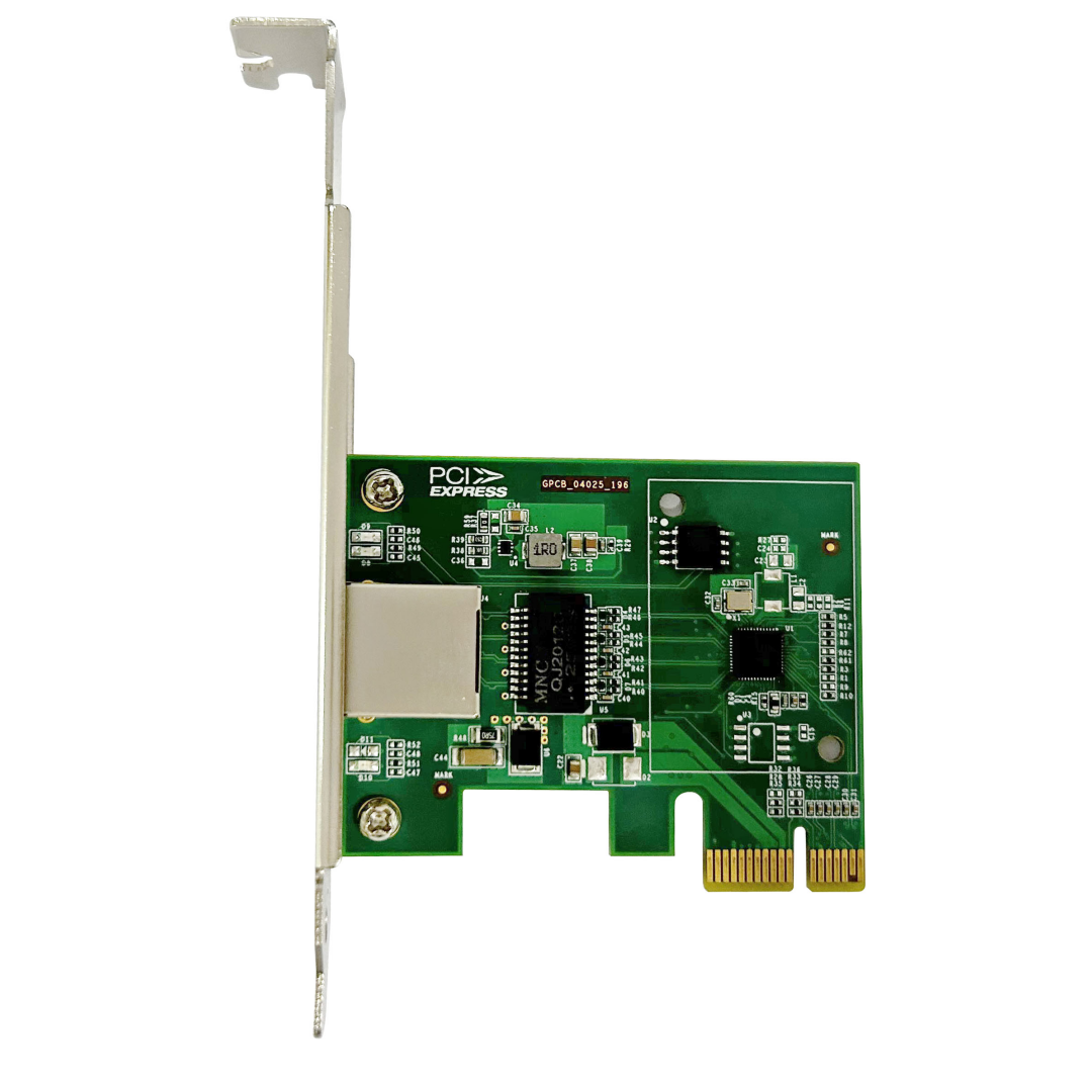
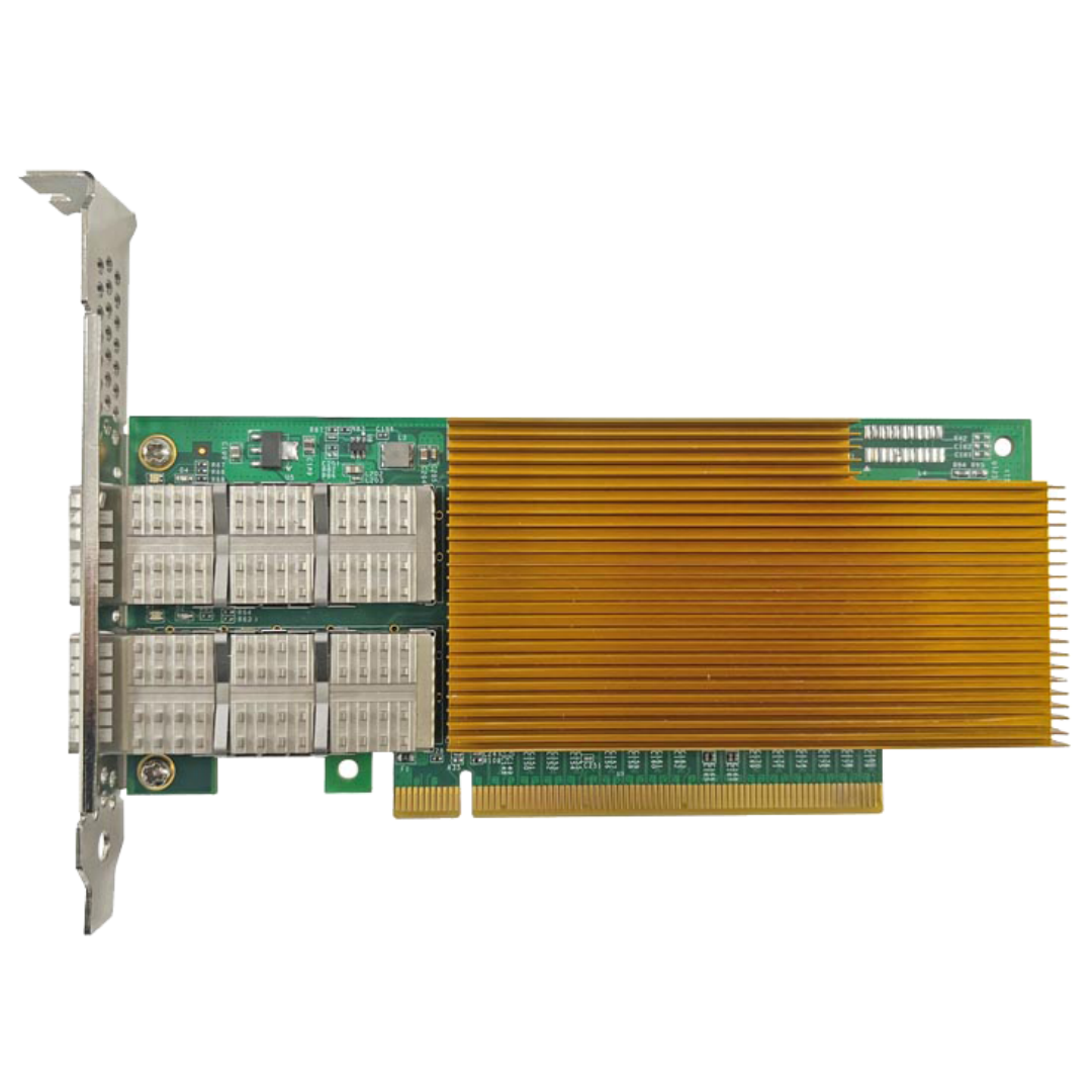
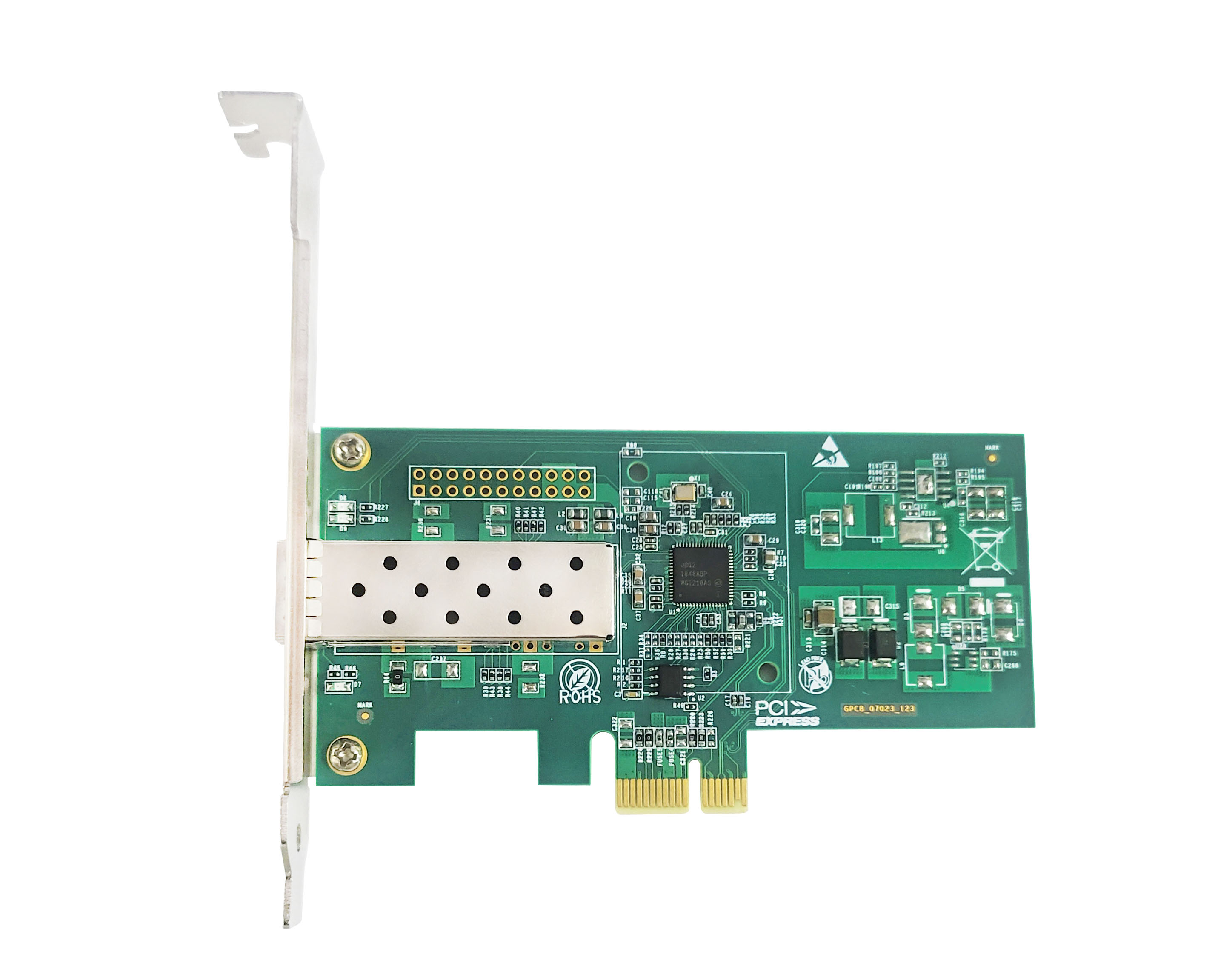
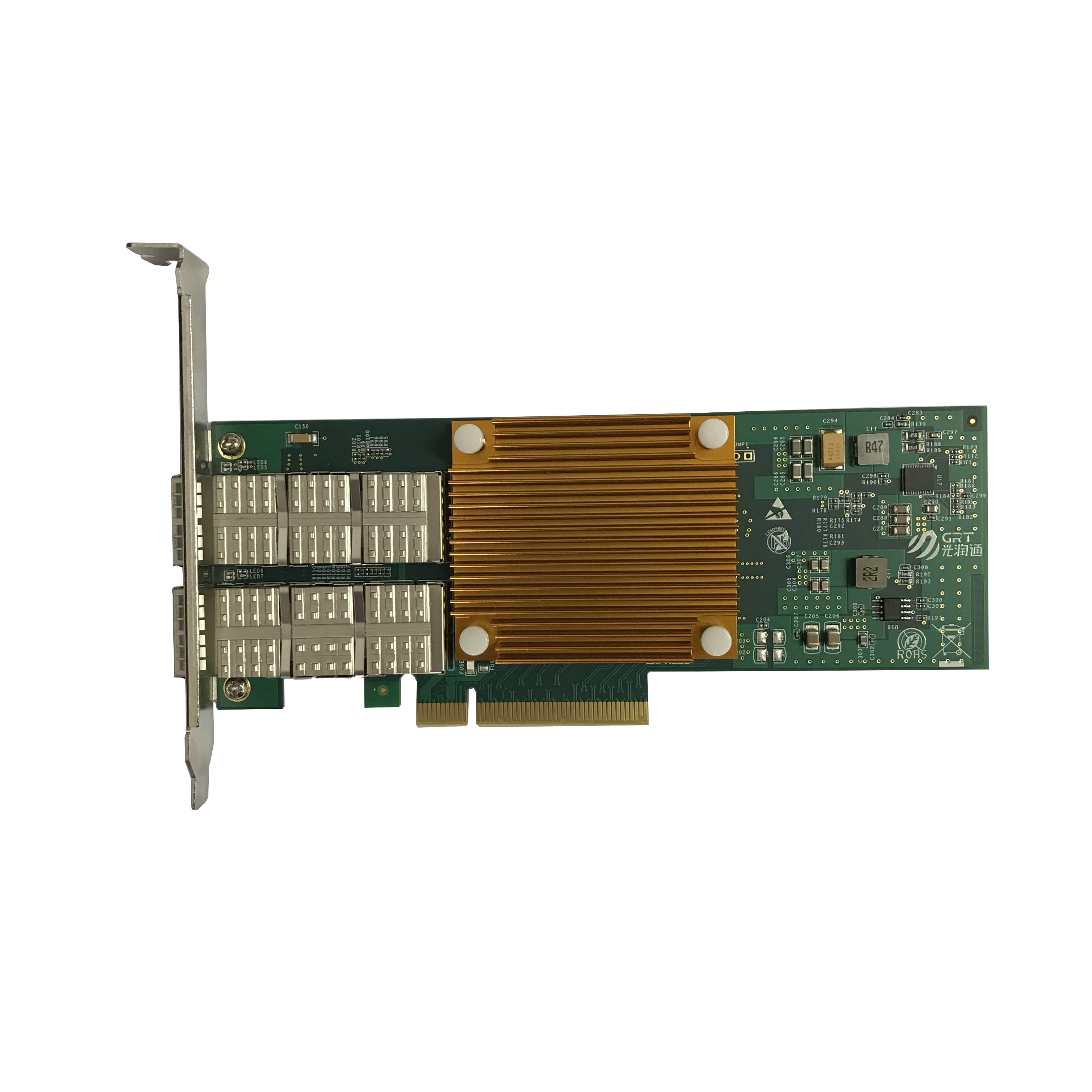

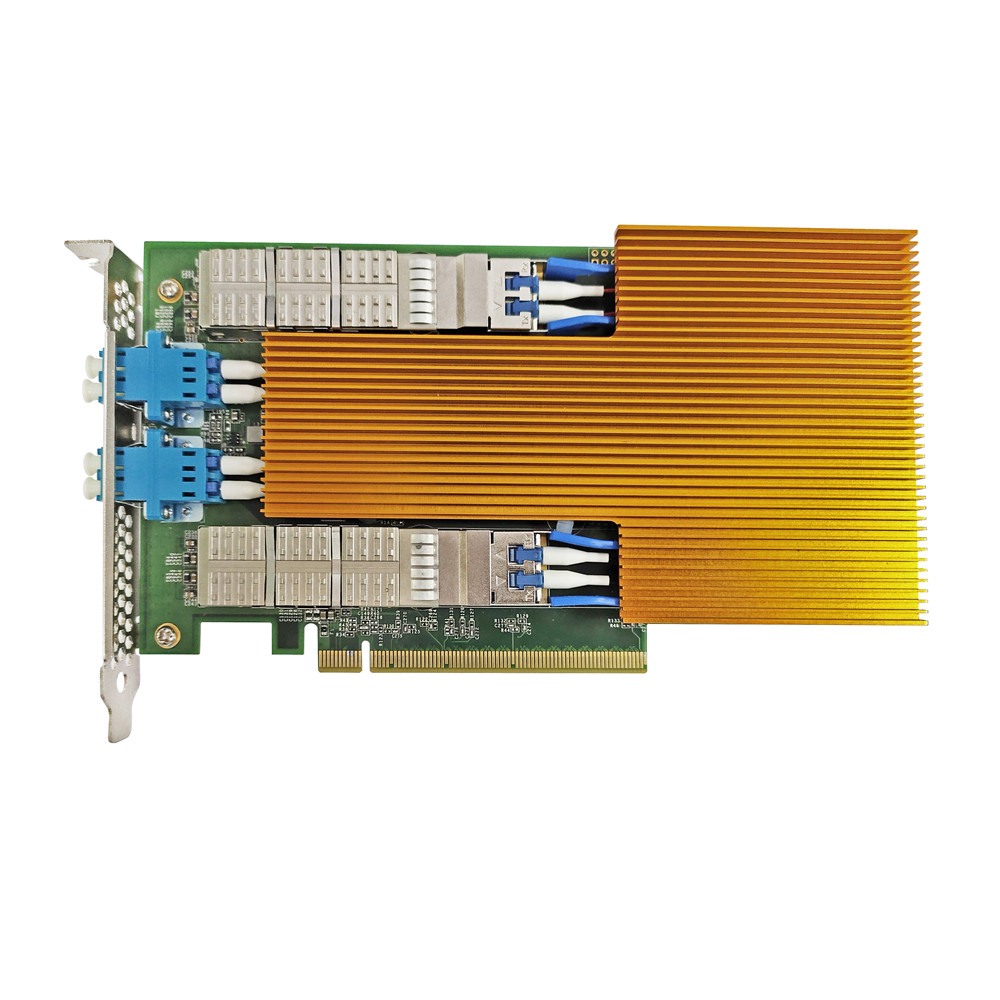
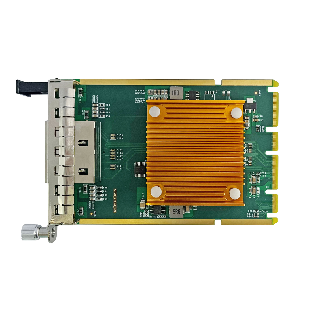
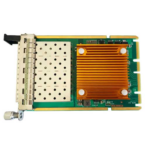
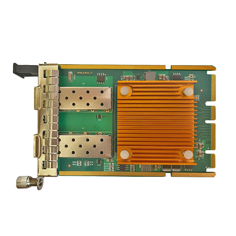
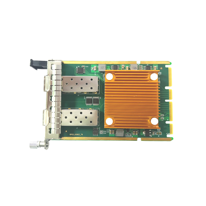
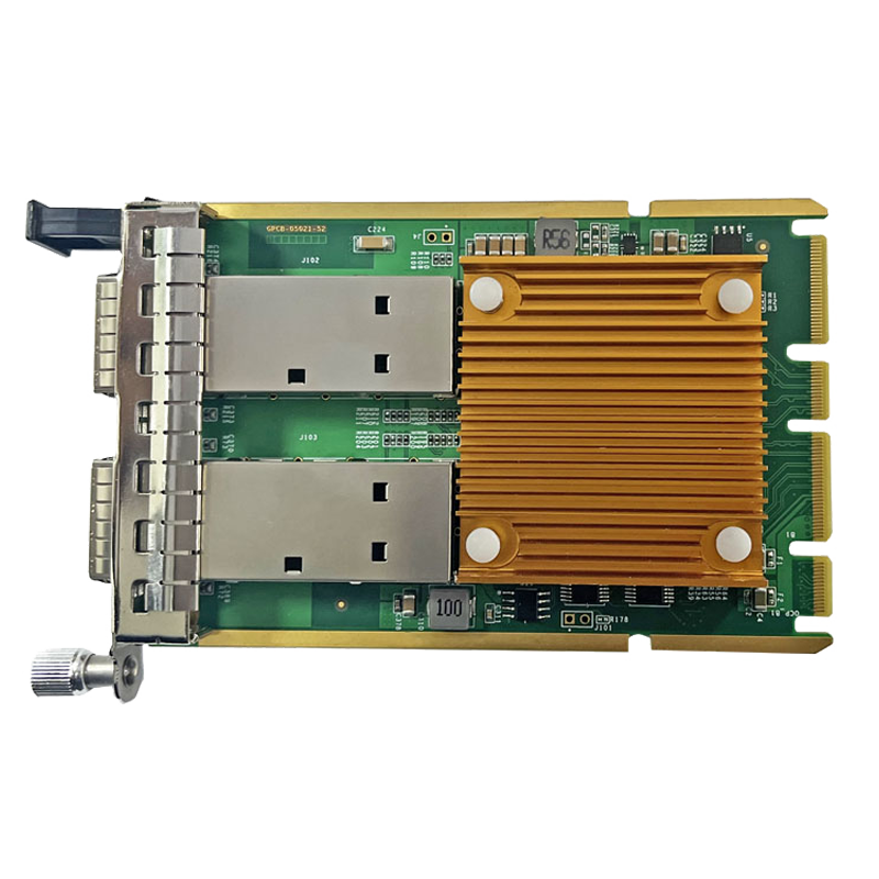
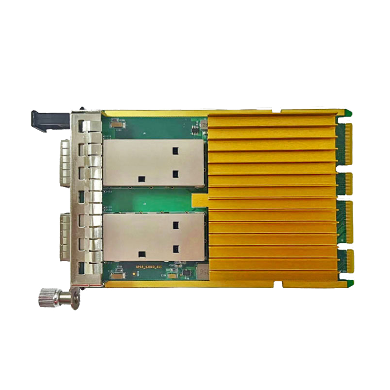
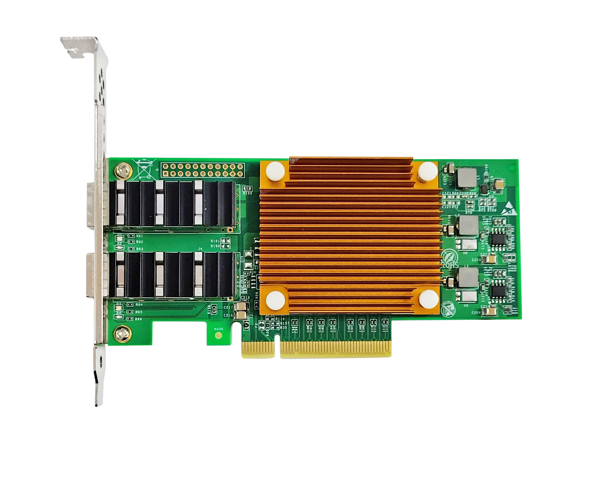
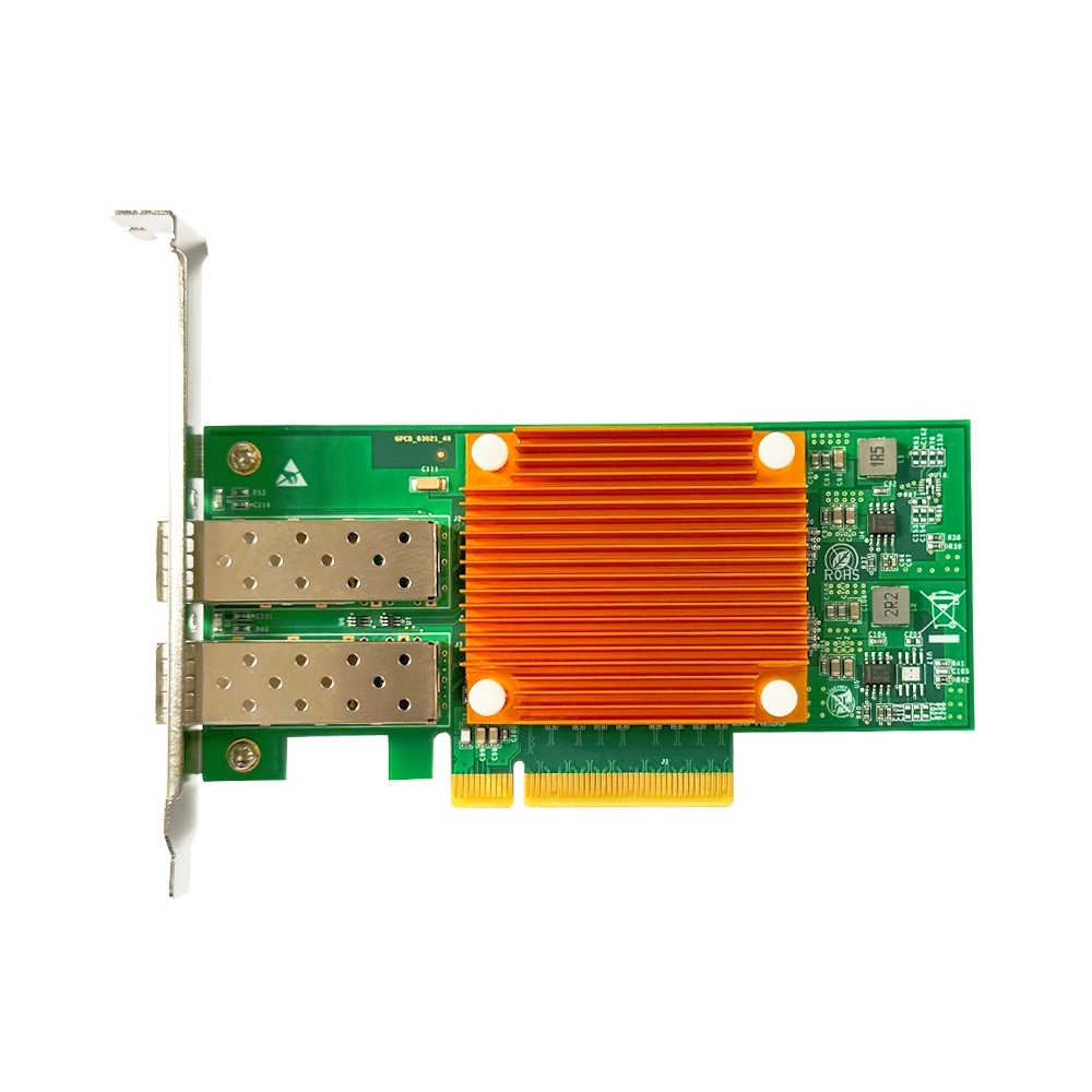
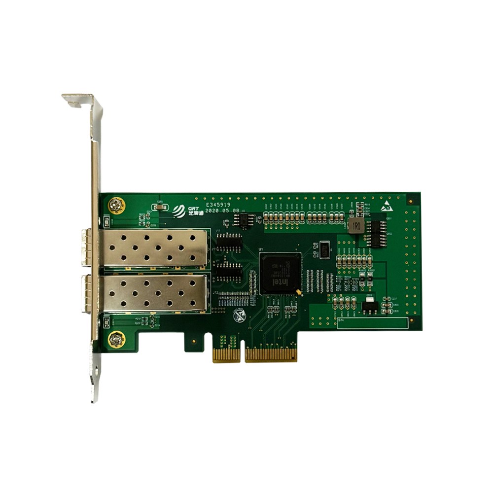

Compatibility Matching Between Fiber Network Cards and Switches
< BackDuring the construction of network systems, the connection between fiber network cards and switches forms the foundation of the entire link. However, this seemingly basic step is frequently the source of network failures. The technical support team of Guangruntong (GRT) Technology has found in daily services that many issues such as network latency, packet loss and even link‑establishment failures stem not from poor device quality, but from negligence in compatibility matching. Today we sort out several key points to note when deploying fiber‑optic networks from a technical specification perspective.
1. Selection and Matching of Optical Transceivers
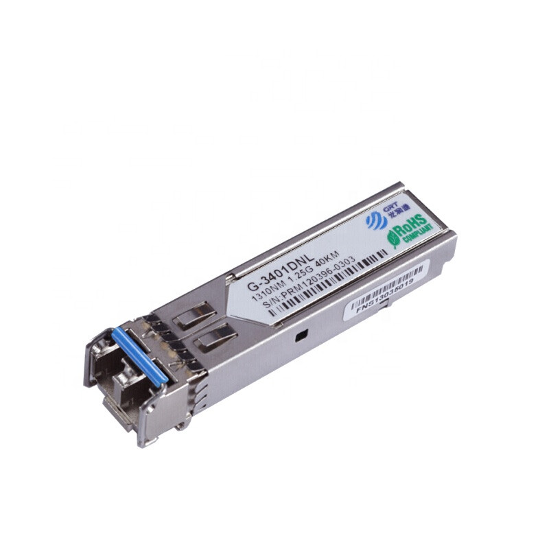
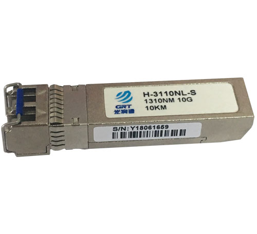
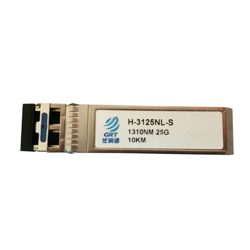
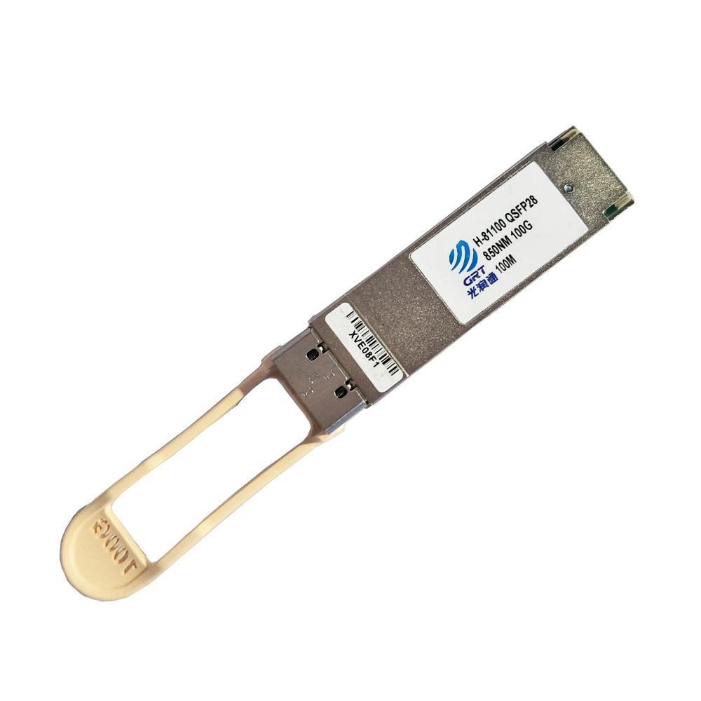
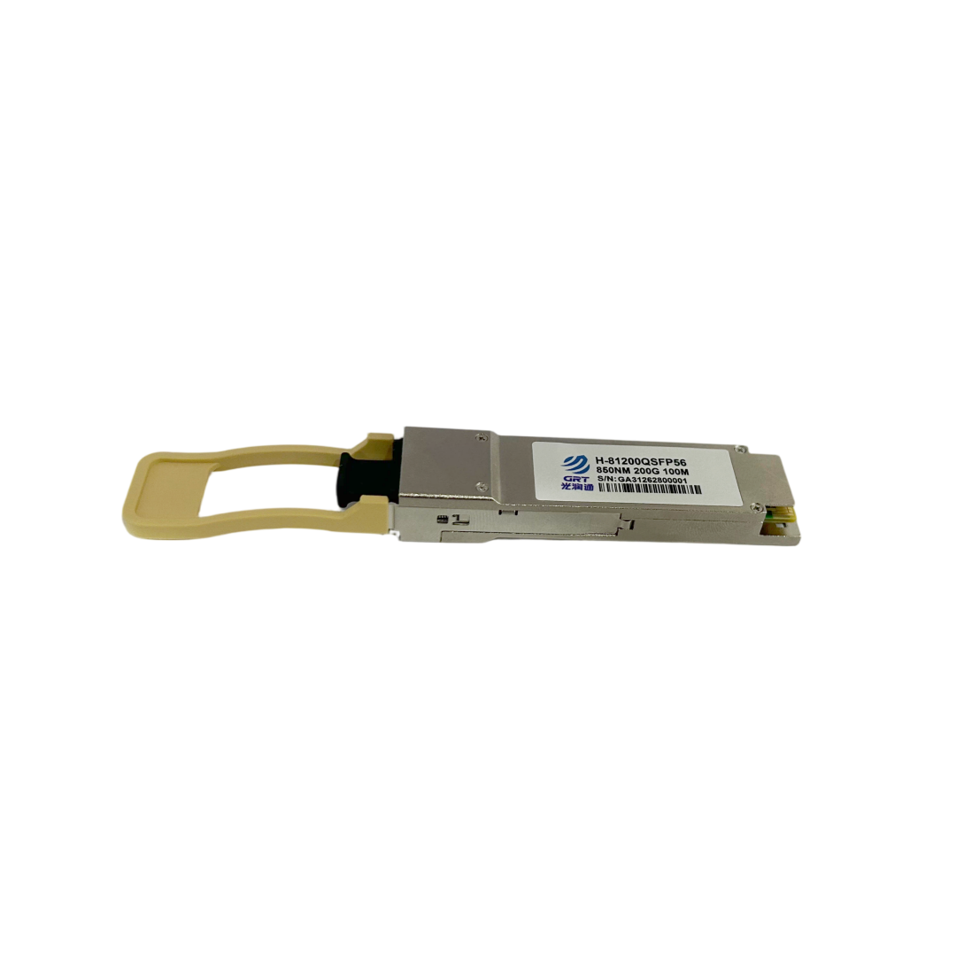
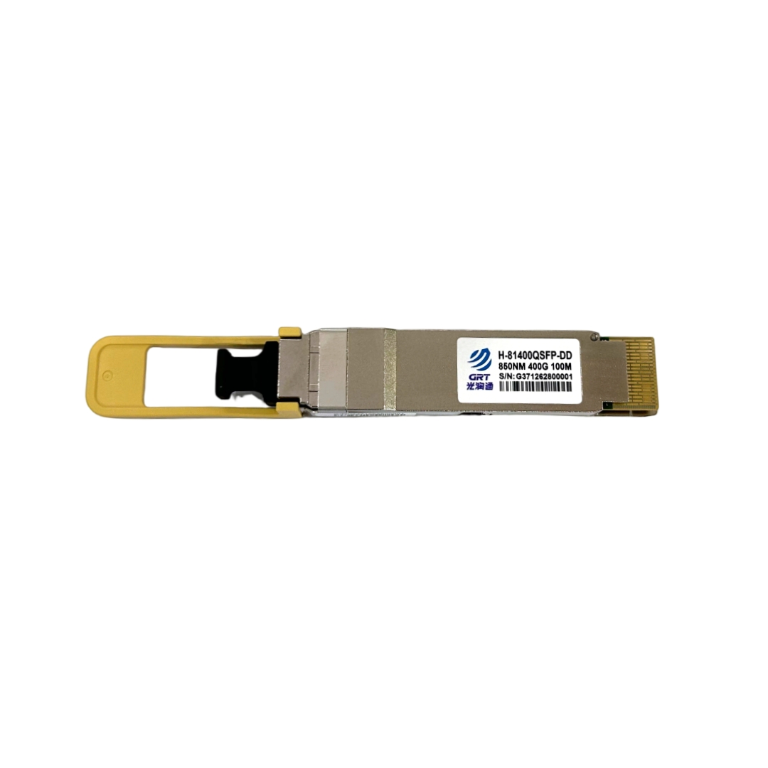
Fiber network cards and switches do not transmit optical signals directly; they rely on plugged‑in optical transceivers (SFP/SFP+). The most common problem here is bidirectional matching of rate and protocol. For example, inserting a 10G transceiver into a 1G network card port. Though sharing the same physical SFP+ form factor, mismatched underlying protocols often result in link failure or abnormal port indicator lights.
Special attention should be paid to encoding schemes. Early Gigabit Ethernet adopts 8B/10B encoding, while 10G Ethernet uses 64B/66B encoding. Inconsistent forced mode settings between network card and switch will trigger massive CRC errors. Guangruntong (GRT) recommends informing suppliers of your network card and switch brands when purchasing transceivers, so that compatible transceiver firmware can be flashed.
2. PCIe Channel Bandwidth Bottleneck
Many users purchase 25G network cards but fail to reach expected throughput in real‑world transmission. The root cause often lies in the server PCIe slot. A dual‑port 25G NIC delivers nearly 100Gbps theoretical bidirectional throughput, which requires at least PCIe 3.0 x8 or PCIe 4.0 x4 slot bandwidth on the server.
Installing a 25G card into a PCIe 2.0 slot, or a physically x16 slot running at electrical x1 (some servers split lanes for expansion), will force the NIC to run at reduced speed. Always check the server motherboard manual to confirm actual electrical lane specifications before installation.
3. Negotiation of Flow Control and Jumbo Frames
After link establishment, performance optimization depends on mutual parameter negotiation. Jumbo Frame is an effective optimization method. If the switch enables 9000‑byte jumbo frames while the NIC keeps standard 1500‑byte MTU, packets will be fragmented and reassembled, greatly increasing CPU overhead.
Flow Control configuration must also be consistent. If Pause Frame is enabled on the NIC but Flow Control is disabled on the switch, pause requests from the NIC will be ignored under congestion. This causes forced packet discarding, TCP retransmission and latency jitter.
4. Impacts of Physical Media
For short‑range transmission, multimode fiber with VCSEL laser is widely used; note the bandwidth difference between OM3 and OM4 fiber. For long‑distance transmission, connector cleanliness of single‑mode fiber is often overlooked. Tiny dust on fiber end faces may carbonize under high‑power laser, bringing signal attenuation or even port burnout.
In conclusion, fiber‑optic network deployment is systematic work requiring end‑to‑end matching covering PCIe, optical transceivers and fiber cables. Guangruntong (GRT) provides high‑performance hardware as well as comprehensive network architecture consulting, helping customers avoid deployment pitfalls and maximize return on network investment.
- Prev: How Enterprise‑Grade Fiber NICs Unlock True Server Performance
- Next: None
Latest information
- Compatibility Matching Between Fiber Network Cards and Switches
- How Enterprise‑Grade Fiber NICs Unlock True Server Performance
- Invisible Details Determine Network Adapter Stability
- What is the PTP Protocol and Which Guangruntong(GRT) Chips Support It?
- We are heading to LEAP 2026 in Riyadh, Saudi Arabia!
- Why Network Adapters Undergo ESD Testing
- NVIDIA Makes Major Investment in Optical Communications; Chinese Semiconductor Industry Faces Historic Opportunity
- Network Bottlenecks in Industrial Control Scenarios: Why Is Fibre Optic More ‘Rugged’ Than Copper Cable?